
How to Create Figure-Ground Maps from Aerial Views
Learn how to use RenderChat to turn aerial urban views into clean figure-ground maps for site analysis, portfolios, and urban design presentations.
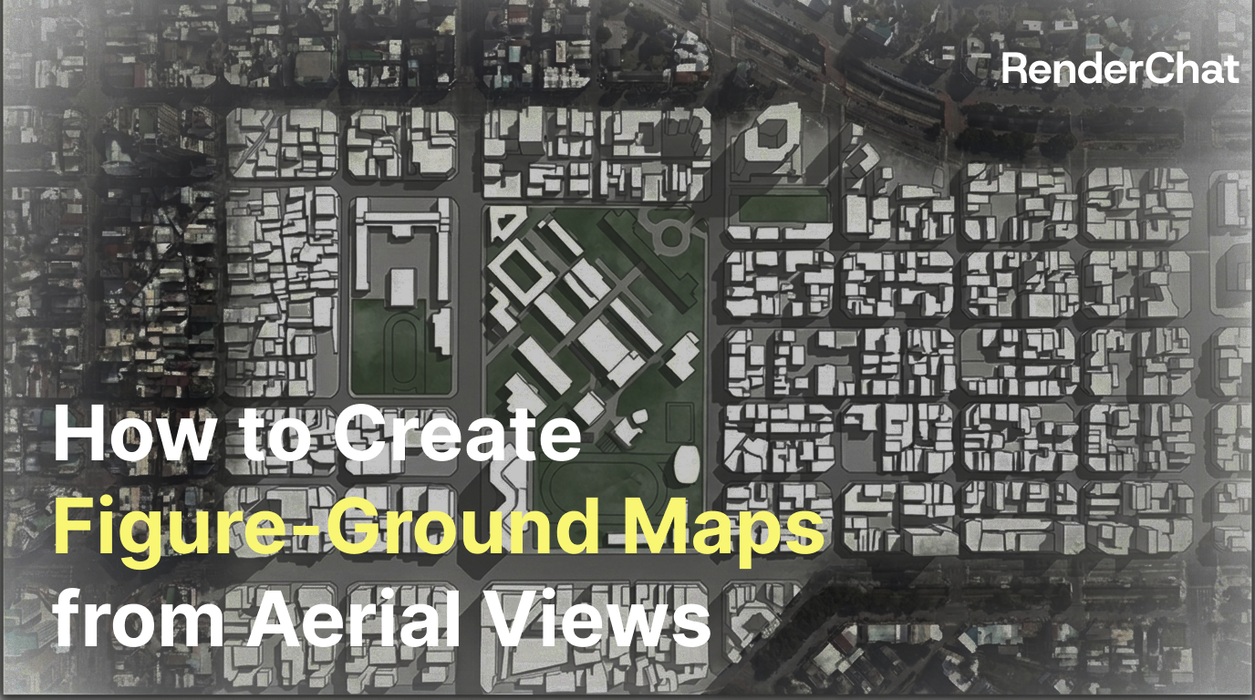
Why create figure-ground maps from aerial views?
In urban design and site analysis, a Figure-ground Map is one of the most useful drawings for understanding urban structure. It simplifies the city into a clear relationship between building mass and open space, helping designers read block density, street continuity, void distribution, and urban fabric.
In practice, however, we do not always start from a clean GIS or CAD file. Many early studies begin with Google Earth, drone footage, or high-angle aerial images. These images contain useful spatial information, but they also include a lot of visual noise: roof textures, cars, tree canopies, shadows, signage, and perspective distortion.
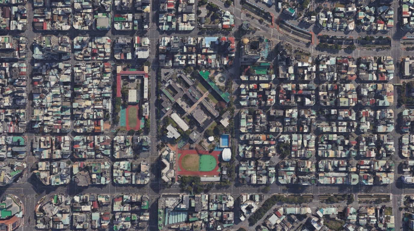 Figure 01. Using a high-angle aerial view as the reference image for urban analysis
In this tutorial, we’ll use ReRender to turn a complex aerial image into a clean portfolio-style Figure-ground Map. The goal is not to replace formal mapping or surveying. Instead, we want to quickly translate real-world urban imagery into a readable analysis base map.
Step 1 — Log in and prepare a clear aerial image
First, log in to RenderChat and prepare a high-angle aerial image of the urban area you want to analyze.

This step is more important than it may seem because the clarity of the aerial image directly affects how the AI reads the urban structure.
Before uploading, check whether building boundaries are clearly visible, streets are continuous, and the overall block structure can be easily identified. Dense tree canopies, strong shadows, vehicles, roof textures, and other visual noise may interfere with the model’s interpretation of building mass and open space.
The best input image is not necessarily the most visually attractive one. What matters is that it clearly shows building footprints, streets, courtyards, open spaces, and block edges.
At this stage, we are not asking the model to create a polished diagram yet. We first want it to clearly understand the existing urban structure.
identify building footprints and open spaces from the aerial urban view, preserve street block structure, simplify roofs and ground texture, remove cars, trees, shadows, and visual noise
Step 2 — Start a new chat and upload the aerial image
After logging in, start a new chat in RenderChat and upload the aerial image as your reference.

Describe what you want in the chat — for example, identifying building footprints, simplifying open spaces, and removing unnecessary visual noise while keeping the original urban structure intact.
RenderChat will use the uploaded aerial image as the spatial reference. The goal is to preserve the existing street network, block proportions, building footprints, and open-space relationships rather than generate a new urban layout.
Once the overall structure is clearly understood, we can move on to defining the visual language of the Figure-ground Map in the next step.
Step 3 — Write the figure-ground prompt
Next, write a prompt that clearly describes the output as a Figure-ground Map.
The most important part is to define what should become “solid” and what should remain “void.” We usually describe buildings as black footprints and open spaces as white areas.
convert this aerial urban view into a clean professional figure-ground map, black building footprints, white open spaces, preserve street layout, urban blocks, building edges, courtyard spaces, and road network, minimal architectural portfolio style, no perspective, no shadows, no labels, no cars, no people, no trees
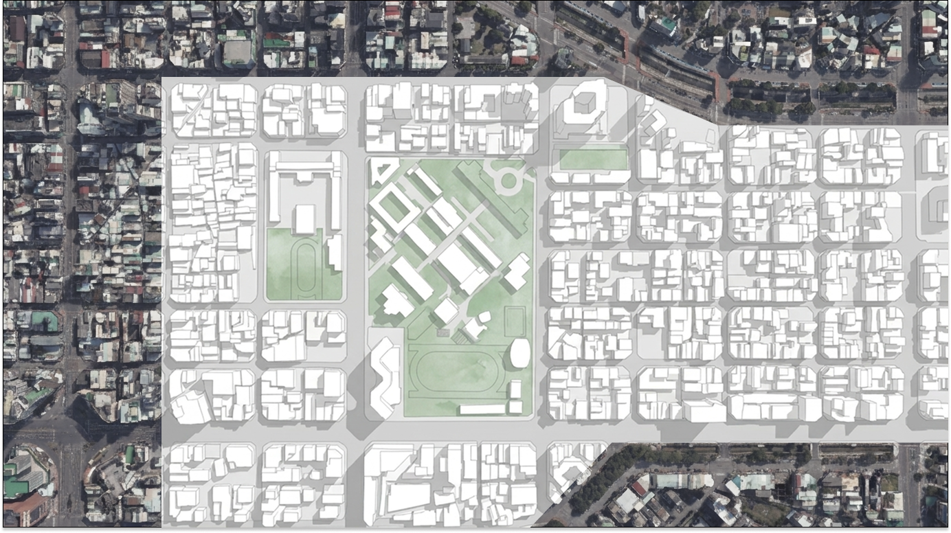 Figure 02. Turning an aerial urban view into a clean Figure-ground Map with ReRender
In our tests, words like black building footprints, white open spaces, and preserve street layout were more useful than simply saying “make it minimal.”
If the prompt only says “minimal city map,” the output may look clean but fail to preserve street proportions or building edges. For urban analysis, that loss of structure matters more than visual polish.
Step 4 — Edit dark corners and bright corners
After the first result is generated, check whether the figure-ground contrast is clear across the whole image.
Sometimes the result may still include dark corners caused by shadows, roof materials, or dense vegetation. In other cases, bright corners may lose building boundaries and turn into overly empty areas.
For dark corners, use an edit prompt that asks the model to simplify shadows and restore the building footprint logic.
clean up the dark corner areas, remove shadow noise, keep only solid building footprints and clear white open spaces, preserve block edges and street layout
For overly bright areas, use a prompt that asks the model to recover missing edges and strengthen the contrast.
recover missing building edges in the bright corner areas, improve figure-ground contrast, keep black building masses and white void spaces, preserve the original urban block structure
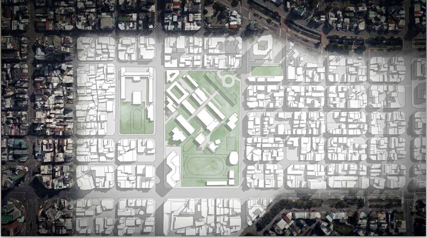 Figure 03. Editing dark and bright corner areas to improve figure-ground readability
This step is important because aerial photos are rarely evenly exposed. If we do not clean up these areas, the final diagram may look minimal but still be unreliable for analysis.
Step 5 — Remove noise and preserve proportions
Figure-ground maps are difficult because real aerial images contain too much information. Roof texture, tree canopies, shadows, parking lots, and road markings all compete with the actual building-open space relationship.
To reduce noise, we usually add restrictions such as remove shadows, remove trees, no roof texture, and flat 2D diagram.
flat 2D architectural analysis diagram, solid black building masses, clean white void spaces, remove roof texture, remove vegetation, remove shadows, preserve urban fabric and block proportions
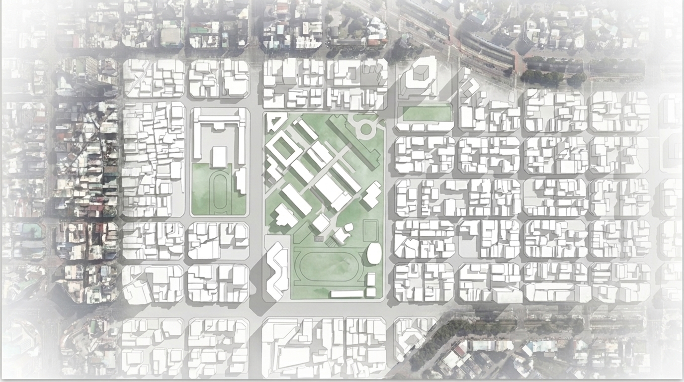 Figure 04. Removing visual noise to create a minimal urban analysis base map
The key trade-off is between cleanliness and accuracy. If the image is too simplified, the block loses important detail. If it is too faithful to the photo, the diagram keeps too much visual noise.
In most cases, we prioritize building edges, street networks, courtyards, and open spaces over roof material or landscape detail.
Step 6 — Use the map for portfolio and site analysis
This workflow can turn a complex aerial city image into a readable Figure-ground Map. It is useful for site analysis, portfolio base maps, urban fabric comparison, block density studies, and early-stage design references.
ReRender still requires manual review for building outlines, road continuity, open space boundaries, and black-white relationships. If the result is used for formal urban research or regulation analysis, designers should still verify it with GIS, CAD, or survey data.
But for early-stage proposals, this workflow can reduce the time needed to turn real aerial imagery into an analysis base map.
AI is not replacing urban analysis here. It helps us translate existing city imagery into a visual language that is easier to read, compare, and discuss.
这篇内容有帮助吗?
相关教程
How to Turn a Floor Plan into a Professional Portfolio Rendering
A cold 2D CAD drawing can become a clean, readable, and presentation-ready floor plan with the right prompt workflow.
Aug 18, 2026
How to Quickly Use the Add People Feature for Realistic Renders
Learn how to use RenderChat to Add People and quickly add realistic figures to your architectural and interior renderings.
Willy·Aug 11, 2026
How to Create Elevation Diagrams from Google Earth
Learn how to use RenderChat and Nano Banana Pro to turn Google Earth street views into clean 2D architectural elevation diagrams.
 Willy·Aug 10, 2026